|
PicoVGA
1.2-cmake
VGA/TV display on Raspberry Pico
|
|
PicoVGA
1.2-cmake
VGA/TV display on Raspberry Pico
|
The following diagram shows how to connect the Pico to VGA:
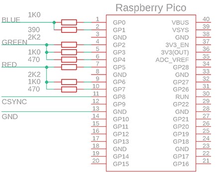
| Pico Pin | Output Wire | Notes |
|---|---|---|
| GP0 | VGA B0 | Resistor 1K0 to Blue output |
| GP1 | VGA B1 | Resistor 390 to Blue output |
| GP2 | VGA G0 | Resistor 2K2 to Green output |
| GP3 | VGA G1 | Resistor 1K0 to Green output |
| GP4 | VGA G2 | Resistor 470 to Green output |
| GP5 | VGA R0 | Resistor 2K2 to Red output |
| GP6 | VGA R1 | Resistor 1K0 to Red output |
| GP7 | VGA R2 | Resistor 470 to Red output |
| GP8 | VGA SYNC | Resistor 100 to HSYNC or CSYNC |
| GP9 | VGA VSYNC | Resistor 100 to VSYNC (if defined) |
| GP19 | PWM sound | RC LOW filter 1K5 resistor + 10n capacitor |
See below for a more detailed wiring diagram
Most demo projects are prepared to control via USB serial port adapter. USB interface is selected in CMakeLists.txt with this command:
Where *target_name* is the name of example target. If instead you want to use the Pico UART for the examples then change the line to the following:
To connect Pico to PC via serial port, you need either convertor from RS232 COM port from 3.3V levels of Pico board, or you need convertor to USB port. Good choice is USB-serial adaptor PL2303TA.
How to connect UART to Pico:
Note: in simple case, you need not diode, you can connect +5V directly on board.
Connect USB/UART adaptor PL2303TA:
| Wire | Pico Pin |
|---|---|
| red | +5V VSYS (39) |
|black |GND (3)| | |white RxD |UART0_TX GP0 (1) | |green TxD |UART0_RX GP1 (2) |
You need serial program to see demo text. Setup port to 115200 Baud, 8 bits, 1 stop bit, no parity, flow control None.
In the Windows Device Manager, USB adaptor can be found under name: "Prolific USB-to-Serial Comm Port (COM10)".
I don't present here the overall circuit I used, because the library was created as part of a retro gaming computer with Raspberry Pico and is still under development. Here is a simplified wiring diagram of the VGA monitor output (with added audio PWM output):
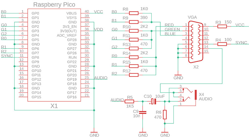
The synchronization output is in the format of the CSYNC synchronization mix (composite synchro, HSYNC + VSYNC). Computer monitors support CSYNC mixed sync. The signal is fed to the HSYNC input (also referred to as CSYNC). An audio output is fed to the VSYNC pin of the VGA connector, for case of output to the TV. The VGA monitor has an input impedance of 75 ohms on this pin, this causes the audio signal to be attenuated and ignored by the VGA monitor and not considered as vertical sync. When the audio connector is inserted, the output to the VGA monitor is disconnected and the audio signal is output to the outside (e.g. to audio headphones).
The TV is connected to the VGA output via a reduction that simply connects the pins of the VGA connector to the corresponding pins of the SCART connector. In this case, the audio signal fed to the VGA connector is also used. Thus, it is not necessary for the device to include a special connector for the TV. The 5V voltage from pin 9 is used as the control voltage for the SCART connector - pin 16 of the SCART connector (Blanking) is connected via a 100 ohm resistor and pin 8 (Switch) is connected directly.
The keyboard connection is not draw here. All sample programs are set up so that program control can be used via the console on the USB virtual port. Simply connect the Pico to the PC via the USB cable used for programming, and run a console program that connects to the USB virtual COM port. For a more detailed description of the connection, see the SDK description.